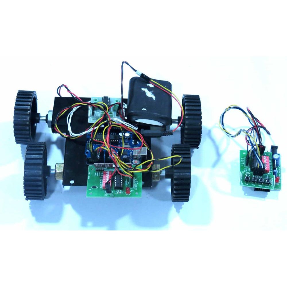
Building a Remote-Controlled Rover Robot with HD12E and HD12D RF Modules
In this project, we'll be building a remote-controlled rover robot using HD12E and HD12D RF modules, L298N motor driver, and an Arduino. The HD12E and HD12D RF modules will facilitate wireless communication between the remote control and the rover robot. The L298N motor driver will control the motors, allowing the robot to move in various directions based on the signals received from the remote control.
Components and Connections
To begin, let's understand the connections between the components:
- L298N Motor Driver:
- OUT1 and OUT2 are connected to the right motor (Red and Black wires).
- OUT3 and OUT4 are connected to the left motor (Red and Black wires).
- 12V, GND, and 5V are connected to a 7805 Power Supply.
- ENA is shorted to 5V.
- IN1, IN2, IN3, and IN4 are connected to Arduino pins D7, D6, D5, and D4, respectively.
- ENB is shorted to 5V.
- HT12D RF Decoder:
- CH1, CH2, CH3, and CH4 are connected to Arduino pins D8, D9, D10, and D11, respectively.
- +ve is connected to the 7805 Power Supply (5V).
- -ve is connected to the 7805 Power Supply (GND).
- Arduino:
- VIN is connected to the 7805 Power Supply (12V).
- GND is connected to the 7805 Power Supply (GND).
Understanding the Arduino Code
The Arduino code is designed to interpret signals from the HT12D RF decoder, which receives inputs from a remote control. Based on the combination of these inputs, the code controls the rover's movement, allowing it to move forward, backward, left, right, or in diagonal directions.
int F = 0; // Variable to store front input
int B = 0; // Variable to store back input
int L = 0; // Variable to store left input
int R = 0; // Variable to store right input
const int L_MOTOR1 = 4; // Left motor forward control
const int L_MOTOR2 = 5; // Left motor backward control
const int R_MOTOR1 = 6; // Right motor forward control
const int R_MOTOR2 = 7; // Right motor backward control
const int F_SWITCH = 8; // Front switch input from HT12D
const int B_SWITCH = 9; // Back switch input from HT12D
const int L_SWITCH = 10; // Left switch input from HT12D
const int R_SWITCH = 11; // Right switch input from HT12D
void setup()
{
Serial.begin(9600);
pinMode(F_SWITCH, INPUT);
pinMode(B_SWITCH, INPUT);
pinMode(L_SWITCH, INPUT);
pinMode(R_SWITCH, INPUT);
pinMode(L_MOTOR1, OUTPUT);
pinMode(L_MOTOR2, OUTPUT);
pinMode(R_MOTOR1, OUTPUT);
pinMode(R_MOTOR2, OUTPUT);
Serial.println("CALIBRATING...");
delay(3000);
Serial.println("DONE");
delay(1000);
}
void loop()
{
F = digitalRead(F_SWITCH);
B = digitalRead(B_SWITCH);
L = digitalRead(L_SWITCH);
R = digitalRead(R_SWITCH);
if (F == LOW && B == HIGH && L == HIGH && R == HIGH) // Front
{
Serial.println("MOVING - FORWARD");
digitalWrite(L_MOTOR1, HIGH);
digitalWrite(L_MOTOR2, LOW);
digitalWrite(R_MOTOR1, HIGH);
digitalWrite(R_MOTOR2, LOW);
}
else if (F == HIGH && B == LOW && L == HIGH && R == HIGH) // Back
{
Serial.println("MOVING - BACKWARD");
digitalWrite(L_MOTOR1, LOW);
digitalWrite(L_MOTOR2, HIGH);
digitalWrite(R_MOTOR1, LOW);
digitalWrite(R_MOTOR2, HIGH);
}
else if (F == HIGH && B == HIGH && L == LOW && R == HIGH) // Left
{
Serial.println("MOVING - LEFT");
digitalWrite(L_MOTOR1, LOW);
digitalWrite(L_MOTOR2, HIGH);
digitalWrite(R_MOTOR1, HIGH);
digitalWrite(R_MOTOR2, LOW);
}
else if (F == HIGH && B == HIGH && L == HIGH && R == LOW) // Right
{
Serial.println("MOVING - RIGHT");
digitalWrite(L_MOTOR1, HIGH);
digitalWrite(L_MOTOR2, LOW);
digitalWrite(R_MOTOR1, LOW);
digitalWrite(R_MOTOR2, HIGH);
}
else if (F == LOW && B == HIGH && L == LOW && R == HIGH) // Front - Left
{
Serial.println("MOVING - FORWARD LEFT");
digitalWrite(L_MOTOR1, LOW);
digitalWrite(L_MOTOR2, LOW);
digitalWrite(R_MOTOR1, HIGH);
digitalWrite(R_MOTOR2, LOW);
}
else if (F == LOW && B == HIGH && L == HIGH && R == LOW) // Front - Right
{
Serial.println("MOVING - FORWARD RIGHT");
digitalWrite(L_MOTOR1, HIGH);
digitalWrite(L_MOTOR2, LOW);
digitalWrite(R_MOTOR1, LOW);
digitalWrite(R_MOTOR2, LOW);
}
else if (F == HIGH && B == LOW && L == LOW && R == HIGH) // Back - Left
{
Serial.println("MOVING - BACKWARD LEFT");
digitalWrite(L_MOTOR1, LOW);
digitalWrite(L_MOTOR2, LOW);
digitalWrite(R_MOTOR1, LOW);
digitalWrite(R_MOTOR2, HIGH);
}
else if (F == HIGH && B == LOW && L == HIGH && R == LOW) // Back - Right
{
Serial.println("MOVING - BACKWARD RIGHT");
digitalWrite(L_MOTOR1, LOW);
digitalWrite(L_MOTOR2, HIGH);
digitalWrite(R_MOTOR1, LOW);
digitalWrite(R_MOTOR2, LOW);
}
else // Stop
{
Serial.println("STOP");
digitalWrite(L_MOTOR1, LOW);
digitalWrite(L_MOTOR2, LOW);
digitalWrite(R_MOTOR1, LOW);
digitalWrite(R_MOTOR2, LOW);
}
}
Initialization
In the setup function, we initialize the necessary pins for motor control and RF signal reception. We also perform an initial calibration by printing "CALIBRATING..." to the serial monitor, waiting for 3 seconds, and then printing "DONE".
Controlling Rover Movement
The main logic is within the loop function, where we constantly read the inputs from the HT12D RF decoder. Based on the combination of these inputs, we determine the movement of the rover and control the motors accordingly.
- Front: Moves the rover forward.
- Back: Moves the rover backward.
- Left: Moves the rover to the left.
- Right: Moves the rover to the right.
- Front - Left: Moves the rover forward and to the left simultaneously.
- Front - Right: Moves the rover forward and to the right simultaneously.
- Back - Left: Moves the rover backward and to the left simultaneously.
- Back - Right: Moves the rover backward and to the right simultaneously.
Stopping the Rover
If no specific movement combination is detected (i.e., all inputs are HIGH or LOW), the rover comes to a stop.
Conclusion
With this Arduino code and the hardware setup, you can control a rover robot wirelessly using an RF remote control and the HD12E and HD12D modules. Experiment with the code and customize it to suit your specific rover robot project.