Building a FS-CT6B Remote Control System Rover Robot (FSCT6B_Rover)
we'll explore how to build a rover robot using the FS-CT6B remote control system and Arduino. We'll delve into the code, understand its components and connections, and discuss how it controls the robot's movement and speed.
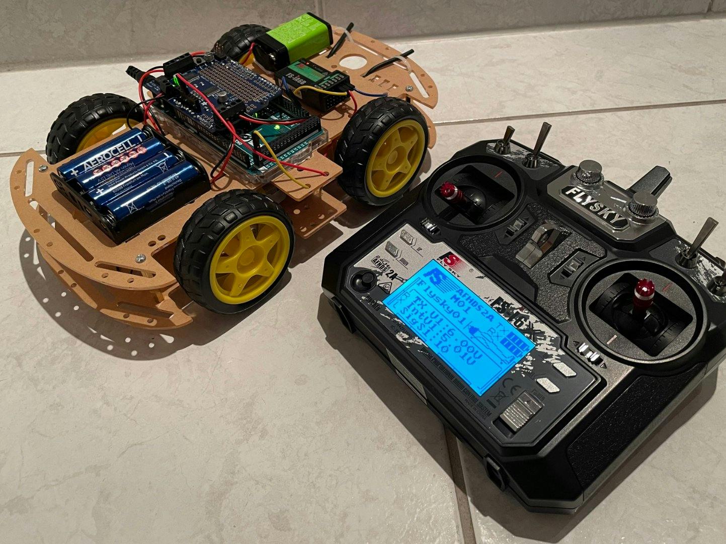
Rover robots are versatile machines that can navigate various terrains and perform tasks remotely. In this project, we use the FS-CT6B remote control system in conjunction with an Arduino board to control the movement and speed of a rover robot. The code provided controls the motors based on the signals received from the remote control.
Components and Connections
The key components and their connections for this project are as follows:
-
L298N Motor Driver:
- OUT1 and OUT2 connected to the right motor (Red and Black wires).
- OUT3 and OUT4 connected to the left motor (Red and Black wires).
- 12V, GND, and 5V connected to the 7805 power supply.
- ENA, IN1, IN2, IN3, IN4, and ENB connected to various Arduino pins for motor control.
-
FS-CT6B Remote Control:
- CH1, CH2, and CH3 connected to Arduino pins for receiving control signals.
-
Arduino:
- VIN and GND connected to the 7805 power supply.
Understanding the Code
The provided Arduino code interprets signals received from the remote control through CH1, CH2, and CH3 pins. These signals dictate the robot's movement direction and speed. Here's a brief overview of the code:
-
Initialization:
- Pins for motor control and serial communication are initialized.
-
Loop Function:
- Reads signals from CH1, CH2, and CH3 using pulseIn().
- Based on the signals received, the code determines the movement (forward, backward, left, right, etc.) and sets the motor controls accordingly.
- The code also adjusts the motor speed based on the CH3 signal.
int CH_1 = 0; // Channel for Front - Back Signal
int CH_2 = 0; // Channel for Left - Right Signal
int CH_3 = 0; // Channel for Speed Control Signal (CH3 - D5)
const int L_MOTOR0 = 6; // Left motor speed control
const int L_MOTOR1 = 7; // Left motor forward control
const int L_MOTOR2 = 8; // Left motor backward control
const int R_MOTOR0 = 9; // Right motor speed control
const int R_MOTOR1 = 10; // Right motor forward control
const int R_MOTOR2 = 11; // Right motor backward control
void setup()
{
Serial.begin(9600);
pinMode(L_MOTOR1, OUTPUT);
pinMode(L_MOTOR2, OUTPUT);
pinMode(R_MOTOR1, OUTPUT);
pinMode(R_MOTOR2, OUTPUT);
}
void loop()
{
CH_1 = pulseIn(3, HIGH);
CH_2 = pulseIn(4, HIGH);
CH_3 = pulseIn(5, HIGH);
if (CH_1 >= 1600 && CH_2 >= 1400 && CH_2 <= 1600) // Front
{
Serial.print("MOVING - FORWARD");
digitalWrite(L_MOTOR1, HIGH);
digitalWrite(L_MOTOR2, LOW);
digitalWrite(R_MOTOR1, HIGH);
digitalWrite(R_MOTOR2, LOW);
}
else if (CH_1 <= 1400 && CH_2 >= 1400 && CH_2 <= 1600) // Back
{
Serial.print("MOVING - BACKWARD");
digitalWrite(L_MOTOR1, LOW);
digitalWrite(L_MOTOR2, HIGH);
digitalWrite(R_MOTOR1, LOW);
digitalWrite(R_MOTOR2, HIGH);
}
else if (CH_2 <= 1400 && CH_1 >= 1400 && CH_1 <= 1600) // Left
{
Serial.print("MOVING - LEFT");
digitalWrite(L_MOTOR1, LOW);
digitalWrite(L_MOTOR2, HIGH);
digitalWrite(R_MOTOR1, HIGH);
digitalWrite(R_MOTOR2, LOW);
}
else if (CH_2 >= 1600 && CH_1 >= 1400 && CH_1 <= 1600) // Right
{
Serial.print("MOVING - RIGHT");
digitalWrite(L_MOTOR1, HIGH);
digitalWrite(L_MOTOR2, LOW);
digitalWrite(R_MOTOR1, LOW);
digitalWrite(R_MOTOR2, HIGH);
}
else if (CH_1 >= 1600 && CH_2 >= 1600) // Front - Right
{
Serial.print("MOVING - FORWARD RIGHT");
digitalWrite(L_MOTOR1, HIGH);
digitalWrite(L_MOTOR2, LOW);
digitalWrite(R_MOTOR1, LOW);
digitalWrite(R_MOTOR2, LOW);
}
else if (CH_1 >= 1600 && CH_2 <= 1400) // Front - Left
{
Serial.print("MOVING - FORWARD LEFT");
digitalWrite(L_MOTOR1, LOW);
digitalWrite(L_MOTOR2, LOW);
digitalWrite(R_MOTOR1, HIGH);
digitalWrite(R_MOTOR2, LOW);
}
else if (CH_1 <= 1400 && CH_2 >= 1600) // Back - Right
{
Serial.print("MOVING - BACKWARD RIGHT");
digitalWrite(L_MOTOR1, LOW);
digitalWrite(L_MOTOR2, HIGH);
digitalWrite(R_MOTOR1, LOW);
digitalWrite(R_MOTOR2, LOW);
}
else if (CH_1 <= 1400 && CH_2 <= 1400) // Back - Left
{
Serial.print("MOVING - BACKWARD LEFT");
digitalWrite(L_MOTOR1, LOW);
digitalWrite(L_MOTOR2, LOW);
digitalWrite(R_MOTOR1, LOW);
digitalWrite(R_MOTOR2, HIGH);
}
else // Stop
{
Serial.print("STOP");
digitalWrite(L_MOTOR1, LOW);
digitalWrite(L_MOTOR2, LOW);
digitalWrite(R_MOTOR1, LOW);
digitalWrite(R_MOTOR2, LOW);
}
if (CH_3 <=1200) // Speed 00
{
Serial.println(" | SPEED - 0%");
analogWrite(L_MOTOR0, 0);
analogWrite(R_MOTOR0, 0);
}
else if (CH_3 <= 1300 && CH_3 >= 1201) // Speed 01
{
Serial.println(" | SPEED - 15%");
analogWrite(L_MOTOR0, 70);
analogWrite(R_MOTOR0, 70);
}
else if (CH_3 <= 1400 && CH_3 >= 1301) // Speed 02
{
Serial.println(" | SPEED - 30%");
analogWrite(L_MOTOR0, 110);
analogWrite(R_MOTOR0, 110);
}
else if (CH_3 <= 1500 && CH_3 >= 1401) // Speed 03
{
Serial.println(" | SPEED - 60%");
analogWrite(L_MOTOR0, 145);
analogWrite(R_MOTOR0, 145);
}
else if (CH_3 <= 1600 && CH_3 >= 1501) // Speed 04
{
Serial.println(" | SPEED - 75%");
analogWrite(L_MOTOR0, 180);
analogWrite(R_MOTOR0, 180);
}
else if (CH_3 <= 1700 && CH_3 >= 1601) // Speed 05
{
Serial.println(" | SPEED - 90%");
analogWrite(L_MOTOR0, 220);
analogWrite(R_MOTOR0, 220);
}
else if (CH_3 >= 1700) // Speed 06
{
Serial.println(" | SPEED - 100%");
analogWrite(L_MOTOR0, 255);
analogWrite(R_MOTOR0, 255);
}
}
Controlling Rover Movement
The code interprets signals from the remote control and translates them into specific movements:
- Forward
- Backward
- Left
- Right
- Diagonal Movements (e.g., Forward-Left, Forward-Right, etc.)
- Stopping the Rover
Controlling Speed
The CH3 signal controls the speed of the rover:
- Speed levels from 0% to 100% are mapped based on the CH3 signal.
- Speed adjustments are achieved using PWM (Pulse Width Modulation) via analogWrite().
Conclusion
With this Arduino code and the right hardware setup, you can control a rover robot's movement and speed using the FS-CT6B remote control system. Experiment with the code and customize it to suit your specific rover robot project.