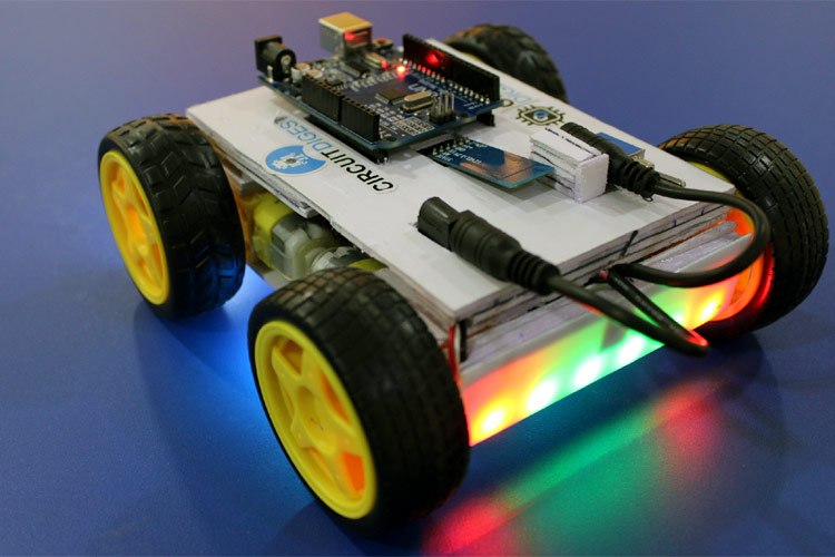
Building a Bluetooth-Controlled Rover Robot with Arduino
Are you fascinated by robotics and want to build your own mobile robot that can be controlled via Bluetooth? In this blog post, we'll guide you through the process of creating a Bluetooth-controlled rover robot using Arduino and an L298N motor driver. Let's dive in and bring your robotic dreams to life!
Components Needed:
- Arduino board
- L298N motor driver
- HC-05 Bluetooth module
- 7805 power supply
- Chassis and motors for the rover
- Jumper wires
Wiring Connections:
Before we start coding, let's ensure the correct wiring connections between the components:
- L298N - OUT1 <--> Right Motor - Red
- L298N - OUT2 <--> Right Motor - Black
- L298N - OUT3 <--> Left Motor - Red
- L298N - OUT4 <--> Left Motor - Black
- L298N - 12V <--> 7805 Power Supply - 12V
- L298N - GND <--> 7805 Power Supply - GND
- L298N - 5V <--> 7805 Power Supply - 5V
- L298N - ENA <--> Arduino - D9
- L298N - IN1 <--> Arduino - D11
- L298N - IN2 <--> Arduino - D10
- L298N - IN3 <--> Arduino - D8
- L298N - IN4 <--> Arduino - D7
- L298N - ENB <--> Arduino - D6
- HC05 - +5V <--> 7805 Power Supply - 5V
- HC05 - GND <--> 7805 Power Supply - GND
- HC05 - TX <--> Arduino - RX (RX0)
- HC05 - RX <--> Arduino - TX (TX1)
- Arduino - VIN <--> 7805 Power Supply - 12V
- Arduino - GND <--> 7805 Power Supply - GND
Arduino Code:
We've written a simple Arduino code to control the motors based on the Bluetooth signals received from the HC-05 module. Here's a breakdown of the code:
- We define pins for motor speed control and direction control.
- In the setup function, we set the pin modes and calibrate the rover.
- In the loop function, we read the Bluetooth signals and control the motors accordingly.
char state = 0; // Variable to store received bluetooth signals
const int L_MOTOR0 = 6; // Left motor speed control
const int L_MOTOR1 = 7; // Left motor forward control
const int L_MOTOR2 = 8; // Left motor backward control
const int R_MOTOR0 = 9; // Right motor speed control
const int R_MOTOR1 = 10; // Right motor forward control
const int R_MOTOR2 = 11; // Right motor backward control
void setup()
{
Serial.begin(9600);
pinMode(L_MOTOR0, OUTPUT);
pinMode(L_MOTOR1, OUTPUT);
pinMode(L_MOTOR2, OUTPUT);
pinMode(R_MOTOR0, OUTPUT);
pinMode(R_MOTOR1, OUTPUT);
pinMode(R_MOTOR2, OUTPUT);
Serial.println("CALIBRATING...");
delay(3000);
Serial.println("DONE");
delay(1000);
}
void loop()
{
if(Serial.available() > 0)
{
state = Serial.read();
}
if (state == 'F') // Front
{
Serial.println("MOVING - FORWARD");
digitalWrite(L_MOTOR1, HIGH);
digitalWrite(L_MOTOR2, LOW);
digitalWrite(R_MOTOR1, HIGH);
digitalWrite(R_MOTOR2, LOW);
}
else if (state == 'B') // Back
{
Serial.println("MOVING - BACKWARD");
digitalWrite(L_MOTOR1, LOW);
digitalWrite(L_MOTOR2, HIGH);
digitalWrite(R_MOTOR1, LOW);
digitalWrite(R_MOTOR2, HIGH);
}
else if (state == 'L') // Left
{
Serial.println("MOVING - LEFT");
digitalWrite(L_MOTOR1, LOW);
digitalWrite(L_MOTOR2, HIGH);
digitalWrite(R_MOTOR1, HIGH);
digitalWrite(R_MOTOR2, LOW);
}
else if (state == 'R') // Right
{
Serial.println("MOVING - RIGHT");
digitalWrite(L_MOTOR1, HIGH);
digitalWrite(L_MOTOR2, LOW);
digitalWrite(R_MOTOR1, LOW);
digitalWrite(R_MOTOR2, HIGH);
}
else if (state == 'G') // Front - Left
{
Serial.println("MOVING - FORWARD LEFT");
digitalWrite(L_MOTOR1, LOW);
digitalWrite(L_MOTOR2, LOW);
digitalWrite(R_MOTOR1, HIGH);
digitalWrite(R_MOTOR2, LOW);
}
else if (state == 'I') // Front - Right
{
Serial.println("MOVING - FORWARD RIGHT");
digitalWrite(L_MOTOR1, HIGH);
digitalWrite(L_MOTOR2, LOW);
digitalWrite(R_MOTOR1, LOW);
digitalWrite(R_MOTOR2, LOW);
}
else if (state == 'H') // Back - Left
{
Serial.println("MOVING - BACKWARD LEFT");
digitalWrite(L_MOTOR1, LOW);
digitalWrite(L_MOTOR2, LOW);
digitalWrite(R_MOTOR1, LOW);
digitalWrite(R_MOTOR2, HIGH);
}
else if (state == 'J') // Back - Right
{
Serial.println("MOVING - BACKWARD RIGHT");
digitalWrite(L_MOTOR1, LOW);
digitalWrite(L_MOTOR2, HIGH);
digitalWrite(R_MOTOR1, LOW);
digitalWrite(R_MOTOR2, LOW);
}
else if (state == 'S') // Stop
{
Serial.println("STOP");
digitalWrite(L_MOTOR1, LOW);
digitalWrite(L_MOTOR2, LOW);
digitalWrite(R_MOTOR1, LOW);
digitalWrite(R_MOTOR2, LOW);
}
else if (state == '0') // Speed 00
{
Serial.println("SPEED - 0%");
analogWrite(L_MOTOR0, 0);
analogWrite(R_MOTOR0, 0);
}
else if (state == '1') // Speed 01
{
Serial.println("SPEED - 10%");
analogWrite(L_MOTOR0, 25);
analogWrite(R_MOTOR0, 25);
}
else if (state == '2') // Speed 02
{
Serial.println("SPEED - 20%");
analogWrite(L_MOTOR0, 50);
analogWrite(R_MOTOR0, 50);
}
else if (state == '3') // Speed 03
{
Serial.println("SPEED - 30%");
analogWrite(L_MOTOR0, 75);
analogWrite(R_MOTOR0, 75);
}
else if (state == '4') // Speed 04
{
Serial.println("SPEED - 40%");
analogWrite(L_MOTOR0, 100);
analogWrite(R_MOTOR0, 100);
}
else if (state == '5') // Speed 05
{
Serial.println("SPEED - 50%");
analogWrite(L_MOTOR0, 125);
analogWrite(R_MOTOR0, 125);
}
else if (state == '6') // Speed 06
{
Serial.println("SPEED - 60%");
analogWrite(L_MOTOR0, 150);
analogWrite(R_MOTOR0, 150);
}
else if (state == '7') // Speed 07
{
Serial.println("SPEED - 70%");
analogWrite(L_MOTOR0, 175);
analogWrite(R_MOTOR0, 175);
}
else if (state == '8') // Speed 08
{
Serial.println("SPEED - 80%");
analogWrite(L_MOTOR0, 200);
analogWrite(R_MOTOR0, 200);
}
else if (state == '9') // Speed 09
{
Serial.println("SPEED - 90%");
analogWrite(L_MOTOR0, 225);
analogWrite(R_MOTOR0, 225);
}
else if (state == 'q') // Speed 10
{
Serial.println("SPEED - 100%");
analogWrite(L_MOTOR0, 255);
analogWrite(R_MOTOR0, 255);
}
}
Uploading the Code:
Once you have the wiring connections set up and the Arduino code ready, upload it to your Arduino board using the Arduino IDE.
Testing the Rover:
Power up your rover and pair your Bluetooth-enabled device with the HC-05 module. Open a serial monitor on your device and send commands (e.g., 'F' for forward, 'B' for backward) to control the rover.
Congratulations! You've successfully built a Bluetooth-controlled rover robot using Arduino and L298N motor driver. Experiment with different commands and expand the functionality of your rover to take it to the next level.